|
|
|
Digital Adders
|
Adding Binary Numbers : -
The basic arithmetic operation in
digital computers is the addition. Because if we can add two binary numbers, we can easily subtract them, or multiply them and perform
division. To do this logical function let us start by adding two binary
bits. Since it is a digital system each bit has only two possible values,
either 0 or 1, there are
22
possible combinations of inputs i.e. four inputs. As you
knew from basic digital logic gates the addition is performed as bellow: The simplest and widely spread circuits which add binary numbers are the half and full adder circuits. They have some differences from each other as you will see later. We can begin with the simpler which is the half adder. Half Adder: - This is an addition circuit which adds two 2-bit values at once. Using analysis techniques we can make different designs for this adder. As we said are adding two bits so, the should have two inputs bits. The results may be one or two bits. Thus, we should have two outputs. One for the sum bit and the other one represents the carry. Now let's name them to construct the truth table for this type of adders: A and B for inputs, Sum and Carry for outputs. Thus, a truth table for half adders can be drawn as bellow:
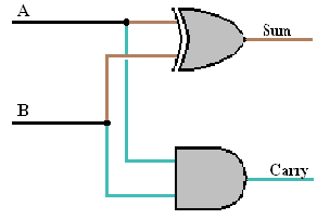
Half Adder Truth Table The first step to converting a truth table to a circuit is to write a Boolean expression. It can be notice that the carry output is a simple AND function, while the Sum is an Exclusive OR gate. These relationships can be expressed using the following equations: Sum = A
Å
B = A'B + AB' Thus, we can use these two gates to add two bits together. The circuit of half adder is shown bellow.
As we said previously this is only one possible design of man other designs. For example, (a): the sum can either be made of two AND gates with the two outputs added with one OR gate and NOT gate, or (b): by two OR gates and one AND gates. These designs can be shown by equations bellow:
(a)
(b) Sum = ( A+B )( A'+B' ) Carry = AB
Full Adders : - When more than two bit binary numbers are added the problem is somewhat more complicated. Then full adder circuit is needed. It is defined by the combinational circuit that forms the arithmetic sum of three inputs, where half adders only add two bits. It consist of three inputs and two outputs. The inputs can be denoted by A, B, and C which represents the carry from the previous lower significant position. The outputs are also Sum and Carry. Thus there will be 23 i.e. 8 possible input and so the truth table will be of five columns and eight rows. This is shown bellow:
Full Adder Truth Table It can be notice from the truth table the sum output is1if an odd number of the three inputs is one, i.e., the Sum function represents XORing for the three inputs. To find the Carry representation we can use the Carno Map. The map will be of eight squares, since it is a function of three inputs. It can be seen by the figure bellow
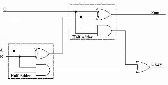
Carry = AB + AC + BC Thus, the Carry can be implemented by three AND gates added with a single OR gate. Where, the Sum is simply two XOR gates. Another possible design is by using two half adders to make a one-bit full adder using additional OR gate, as shown bellow:
So it is now clear what is meant by half and full adder and you can do the lab for more convenient understanding. Go to the half adder lab, then to the full adder virtual lab. |
||||||||||||||||||||||||||||||||||||||||||||||||||||||||||||||||||||||||||||