|
|
|
|
Basic Logic Gates |
|
Binary logic deals with variables that take on
two discrete values and with operations that assume logical meaning. The two
variables take may be called by different names (e.g., true and false, yes
and no, 0 and 1,etc.). Binary logic is used to describe the manipulation and
processing of binary number mathematically. It is particularly suited for
the analysis and design of digital systems, and it consists of binary
variables (A,B,etc.) and logical operations (AND, OR, NOT, etc. ).There are four basic logic gates: AND, OR, XOR, and NOT. Also,
there is another three basic types comes from the previously mentioned
gates they are: NAND, NOR, and
XNOR. We can talk about them in details taking each gate alone.
|
|
|
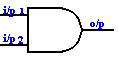
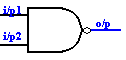
I/P 1 |
I/P 2 |
O/p |
|---|---|---|---|
|
0 |
0 |
0 |
|
|
0 |
1 |
0 |
|
|
1 |
0 |
0 |
|
|
1 |
1 |
1 |
|
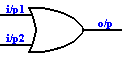
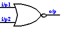
The OR gate is logic operation that is represented by plus sign(+) e.g., A+B. It means that the result will equal 1 if any one or more of the inputs are equals1. The following figure show the circuit symbol and for an OR gate and the truth table for it. It is sort of the reverse of the AND gate. It may be represented by two switches connected in parallel form and that if one switch is closed the current flows and if you have a lamp it will light. The symbol to the left designates the OR gate. As with the AND function, the OR function can have any number of inputs. However, practical commercial OR gates are mostly limited to 2, 3, and 4 inputs, as with AND gates.
|
|
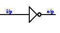
The NOT Gate, or Inverter:
- |
|
|
i/P |
o/p |
|---|---|---|
|
0 |
1 |
|
|
1 |
0 |
|
The
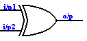
Exclusive-OR, or XOR Gate: - |
|
|
i/P 1 |
i/P 2 |
o/p |
|---|---|---|---|
|
0 |
0 |
0 |
|
|
0 |
1 |
1 |
|
|
1 |
0 |
1 |
|
|
1 |
1 |
0 |
|
The NAND Gate:
- |
|
|
i/P 1 |
i/P 2 |
O/p |
|---|---|---|---|
|
0 |
0 |
1 |
|
|
0 |
1 |
1 |
|
|
1 |
0 |
1 |
|
|
1 |
1 |
0 |
|
|
|
|
i/P 1 |
i/P 2 |
o/p |
|---|---|---|---|
|
0 |
0 |
1 |
|
|
0 |
1 |
0 |
|
|
1 |
0 |
0 |
|
|
1 |
1 |
0 |
|
The
Exclusive-NOR Gate: - |
|
|
i/P 1 |
i/P 2 |
o/p |
|---|---|---|---|
|
0 |
0 |
1 |
|
|
0 |
1 |
0 |
|
|
1 |
0 |
0 |
|
|
1 |
1 |
1 |
|
Basic Logic Gates Experiment:: - |
|
|
|
Digital Design And Analysis Techniques:- After you denote your output function from the truth table, you can then simplify it using this rules to make your circuit as simple as possible. The output function is demonstrated from the truth table by selecting all the outputs those equal the logic "1" and gives there summation .
|