|
|
|
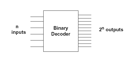
Decoder
|
A single n-to-2n decoder to generate the minterms, OR gate forms the sum. The output lines of the decoder corresponding to the minterms of the function are used as inputs to the OR gate.
Can be implemented with an n-to-2n decoder with m OR Gates. it's Suitable when a circuit has many outputs, and each output function is expressed with few minterms. Note In this lab 3-to-8 line decoder used, uses 3 inputs and 8 leds at any time only one led is active, as we can see from the truth table below. The circuit representation in form of AND & NOT gates is shown below. In the experiment we use a black rectangle to represent the decoder (for simplicity). Truth table
In the 3_to_8 decoder applet below click to turn it on by selecting the ON button in the upper left of the applet. Then, make your desire combination of binary digits for the values of the 3 inputs X, Y, and Z and then see the resulted output, which indicates by LED. LED: Stands for Light Emitting Diode it has a wide use in optical communications and it is also used in digitallaboratories as indicator for the output .When it is ON it indicates a 5 volt level, high level volt (logic"1"), and OFF state represents a low level voltage (logic "0"). The Experiment | ||||||||||||||||||||||||||||||||||||||||||||||||||||||||||||||||||||||||||||||||||||||||||||||||||||||||||||||